AEMC C.A 6116N Electrical Installation Safety Tester with AC and A-Type RCD Testing
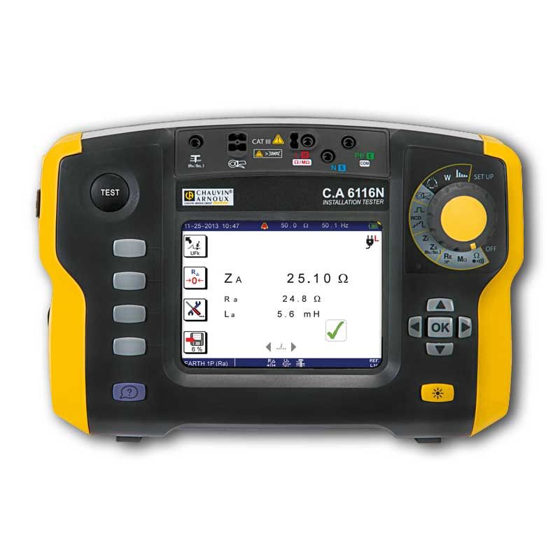


AEMC C.A 6116N Electrical Installation Safety Tester with AC and A-Type RCD Testing
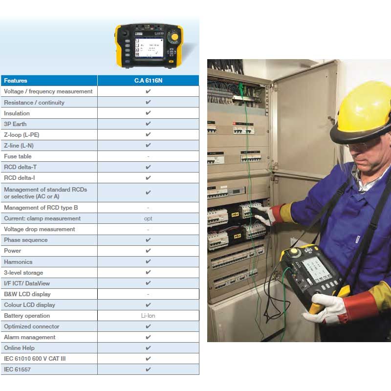
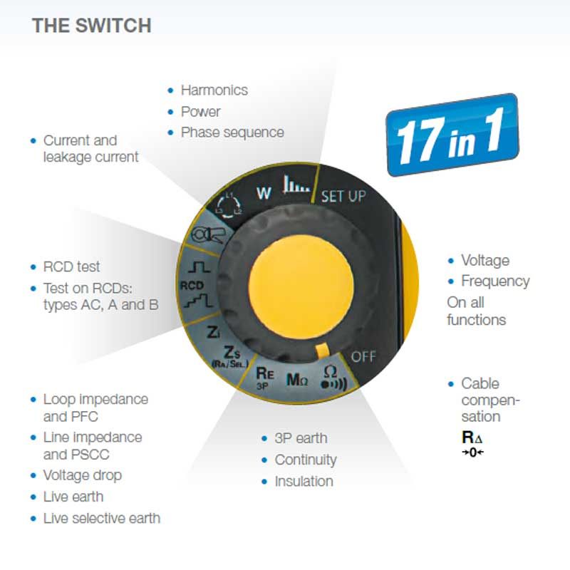
All in one tester that measures: Voltage, Frequncy, Resistance, Continuity, Insulation (megohmmeter), 3 point Earth Resistance, Loop Impedance, Line Impedance, A type RCD, Phase Sequence, Power & Harmonics.
- Testing according to the international standards: IEC 60364-6, NF C 15-100, VDE 100, XP C 16-600, etc.
- Simple, reliable connection thanks to the contextual help for each function, including all the connection diagrams
- Suitable for all neutral systems (TT, TN, IT)
- Type-A RCD testing
- Integrated fuse table for quick reading of the results on the instrument
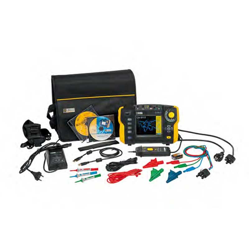
- Li-Ion battery for a longer battery life
- Measurements: voltage, current via clamp, power, waveforms and harmonics.
- Measurement of voltage drop for correct sizing of conductor diameters
- Loop measurement with 1 mΩ resolution
- 3-level storage
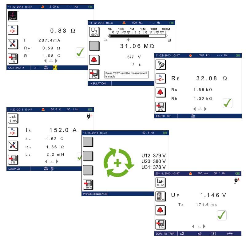
CONTINUITY The purpose of this measurement is to check the resistance of the chassis-earth conductor (PE) which drains faults to earth. This resistance must be lower than a threshold specified by the applicable standard for the installation tested, which is usually 2 Ω as indicated at the top of the screen. As required by the standards, the testers perform the measurement with a minimum current of 200 mA and a no-load voltage of 4 to 24 V.
INSULATION This measurement can be used to check that the insulation resistance is greater than a minimum value specified in the installation standards (insulation measured between active conductors and between an active conductor and the earth). The testers offer 5 different test voltages (50 / 100 / 250 / 500 / 1,000 V) so that they can adapt to all types of installations (ELV, lowcurrent domestic or industrial installation). The test current complies with the IEC 61557 standard. By default, insulation measurement is performed at 500 V with an alarm at 0.5 MΩ. Thanks to the dual display (digital and bargraph with logarithmic scale), users can view a quick estimate of the result during the test. Automatic detection of any voltage present and automatic discharging after the test ensure that users remain safe.
3P EARTH MEASUREMENT Correct earthing guarantees user safety and also protects property and installations in the event of lightning or fault currents. It must always be linked to a cut-off device. There are many different methods for earth measurements and choice of the right one depends on the type of neutral system, the type of installation (domestic, industrial, urban, rural, etc.) and the possibility of cutting off the power supply. 3-pole earth measurement using 2 auxiliary stakes (also known as the 62 % method) is the earth measurement of reference which yields a precise resistance value for the earth electrode. As it is performed with the power off, this is the only earth measurement possible on an installation which has not yet been hooked up to the electrical power distribution network or which is no longer connected to it. Once the cables have been connected, implementation is particularly simple. All you have to do is set the rotary switch to RE 3P, press test and read off the result. Users can choose the test mode: quick or expert. In expert mode, the resistance values of the auxiliary stakes RS and RH are also measured.
EARTH MEASUREMENT ON LIVE CIRCUIT: Ra (1P) Equivalent to 3P earth measurement, the function for earth measurement on a live circuit saves considerable time: it is not necessary to disconnect the earth bar and only requires a single auxiliary stake (S). Furthermore, this method also ensures that people and property remain safe because the earth is not disconnected. The 1P stake must be located outside the area of influence of the earth to be measured. Two modes are available: - Measurement without tripping with low current (6, 9 or 12 mA) for installations protected by 30 mA RCDs, - Measurement with high current (TRIP) providing better measurement accuracy. It is then possible to calculate the fault voltage in the event of a Ufk phase-earth short-circuit as defined in the SEV 3755 standard. - RA low current and ZA high current
Zs LOOP IMPEDANCE The Zs measurement represents the impedance of the Phase-Earth loop (L-PE). This measurement allows you to: - estimate the earth value easily and quickly without setting up any stakes for a TT-type installation - calculate the short-circuit current and size the circuit-breaker for the installation (TN-type installation). This measurement is not possible on an IT-type installation, however, because of the high earthing impedance of the power supply transformer or even its total isolation in relation to the earth. By default, the Zs loop measurement is a measurement without tripping of the 30 mA RCDs (test current = 12 mA) with an alarm threshold of 100 Ω. In addition, the Zs switch position also offers the live earth measurement functions (Ra and Ra Sel) thanks to automatic detection of the auxiliary stake S and the current clamp. For greater safety, in the event of incorrect connection or the presence of a hazardous voltage, the instrument displays an error message to warn the user.
Zi LINE IMPEDANCE & VOLTAGE DROP The Zi measurement represents the impedance of the Phase-Neutral loop (L-N) or the loop between phases (L-L) and can be used to calculate the short-circuit current in order to check the protective systems set up on the installation (fuse or circuit-breaker). This measurement is performed in high-current mode (TRIP mode) to ensure measurement accuracy. The connection can be made either via the three-point/mains lead or by using separate leads for the measurements on electrical cabinets. It is possible to measure the voltage drop in the cable or conductor. This serves to determine whether the cross-section of the conductor is sufficient for the installation. The result of this ΔV measurement is displayed in %; if the value is greater than 5 % or a programmed value, the sizes of the cables for the installation must be recalculated.
RCD TEST (TYPES AC, A and B) 3 types of test are available: - test in pulse mode: measurement of tripping time - test in ramp mode: measurement of tripping time and precise value of the tripping current - non-trip test: to check that the circuit-breaker is not tripped when the leakage current is below the trip threshold, i.e. IΔn/2. The RCD test also allows you to calculate the fault voltage Uf, such that: Uf = Zs x IΔn To perform this test in Ramp mode, the switch must be set to IΔN. In pulse mode, the switch must be set to Δt. Various parameters can be set for this measurement: - calibre of the RCD tested - RCD type: STD (standard), S or G (models only tested with a current of 2 IΔN), AC, A or B. - type of test signal: AC , pulsed or DC - activation/deactivation of the Volt beeper in Ramp mode - activation/deactivation of the alarms in pulse mode
PHASE ROTATION On a three-phase network, this measurement can be used to check the phase sequence on the network. The tester checks the frequency of the 3 signals and then compares them to detect their sequence (negative or positive).
POWER The power measurements offered by the instrument are particularly useful for initial analysis of the energy quality on the installation concerned. Power measurement can be selected by setting the switch to W. It is then possible to view the corresponding voltage and current curves.
HARMONICS The tester can measure harmonics up to the 50th order and displays the graph. The THD-F, THD-R and voltage values are displayed simultaneously, along with the name of the line selected and its amplitude. In this mode, users can choose between FFT analysis of the voltage or the current and display with a linear or logarithmic scale.
| Weight | 8.000000 |
|---|---|
| Specifications | CONTINUITY / RESISTANCE |
| size | 11.02 x 7.48 x 5.04" (4.85 lbs) |
| Power Supply | Rechargeable Li-ion Batteries |
| Manufacturer | AEMC |
| MPN | C.A 6116N |
| Manufacturer Warranty | 1 Year |
| upc code | 685338250039 |